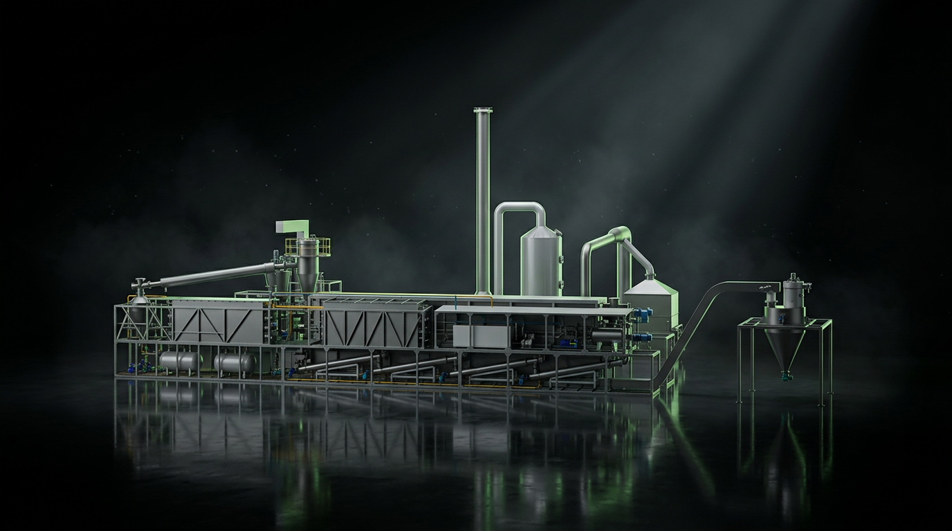
Continuous waste tyre pyrolysis plant — cinematic showcase
// PU500Pyro Systems · Flagship

Continuous Waste TyrePyrolysis Plant.

Industrial-grade continuous pyrolysis engineered to transform end-of-life tyres into oil, carbon black, steel and self-sustaining syngas — at scale, around the clock.

PU500
Model
35–50 TPD
Capacity
25 Days
Continuous Cycle
250 kW
Installed
02The Product

Industrial-grade continuous tyre pyrolysis technology.

Engineered by Pyro System

A fully automated thermal decomposition platform — designed for large-scale, uninterrupted recycling operations.
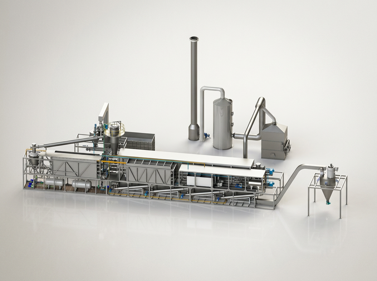
// PU500 · Studio Reference
Pyro Systems
Pyro System PU500 continuous pyrolysis plant

The Continuous Waste Tyre Pyrolysis Machine is an advanced industrial recycling solution designed to convert waste tyres into valuable resources through a continuous thermal decomposition process.

Developed under the Pyro System technology platform, the plant is engineered for large-scale waste tyre recycling while ensuring operational efficiency, safety, environmental compliance, and consistent performance.

The system processes shredded tyre chips and converts them into pyrolysis oil, recovered carbon black, steel wire, and syngas through a fully automated continuous operation.

Capability
Continuous
Operation
Capability
Automated
Process Control
Capability
Closed-Loop
Energy Reuse
03How It Works

An engineered process, orchestrated end-to-end.

Continuous Waste Tyre Pyrolysis · Process Flow

Feedstock enters the system, moves through reactor and recovery stages, and exits as four industrial outputs — continuously, around the clock.

// PU500 · Continuous Pyrolysis Machine
Feed & heat pathGas & emission pathSolid recovery path
04Technical Specification

Engineered to specification.

Every dimension, power rating and material choice is calibrated for stable continuous operation at industrial scale.

01
Model
PU500
02
Capacity
35–50 Tons Per Day
03
Feedstock
20 mm Tyre Chips with wire (max 2%)
04
Voltage
440V / 50Hz (Customized)
05
Weight
Approx. 200 Tons
06
Electric Power Consumption
250 kW Installed
07
Additional Fuel For Startup
Heavy Fuel Oil / Diesel
08
Minimum Machine Area Required
Approx. 50 m × 20 m
09
Building System
Not compulsory
10
Operating Cycle
25 Days Continuous Operation
11
Electronic Control System
PLC + SCADA Control System
12
Fuel Oil Consumption
100–150 kg per hour during startup
13
Reactor Shell Thickness
20 mm
14
Reactor Shell Length
28 m × 2 m
15
Cooling Method
Water Cooling
05Advantages

Built for industrial endurance.

Mechanical, thermal and process engineering — refined to deliver predictable output, day after day.

01

Continuous Internal Rotation Structure

02

Thermal Heating Distribution Technology

03

High Efficiency and Durability

04

Stable Operation and Reliable Output

05

External Rotating Wheel System

06

Long-Term Continuous Operation

07

Environmentally Friendly Gas Management

08

Large-Scale Industrial Processing Capability

06Output & Applications

From waste tyre to recovered value.

Four industrial outputs recovered through a single continuous process — each re-entering the value chain.
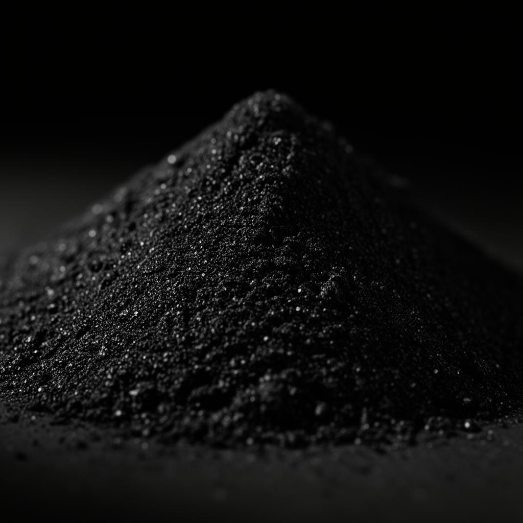

Pyrolysis Oil
// 01Yield 40–45%

Pyrolysis Oil

Applications
  • Industrial Fuel
  • Refinery Feedstock
  • Fuel Processing Industries
Carbon Black
// 02Yield 30–35%

Carbon Black

Applications
  • Rubber Industry
  • Plastic Industry
  • Ink Manufacturing
  • Coating Industry
Syngas
// 03Yield 10–15%

Syngas

Applications
  • Internal Fuel Source
  • Plant Heating
  • Reduced Operating Costs
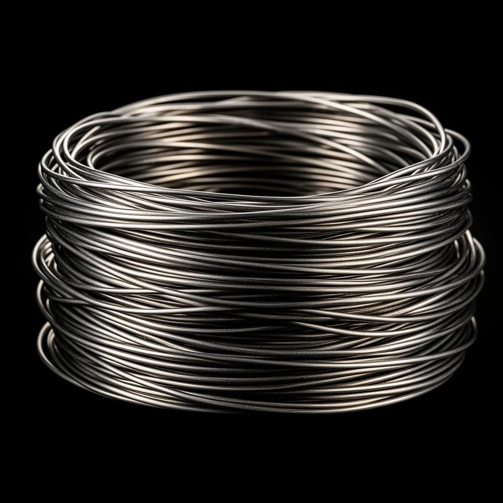
Recovered Steel
// 04

Recovered Steel

Applications
  • Steel Recycling
  • Metal Fabrication
  • Industrial Reuse
07Product In Action

See the system in operation.

Experience the continuous pyrolysis process through real-world installation and operational footage.

Continuous Pyrolysis Plant — operation preview
// REC · 4K · Plant Walkthrough
Featured Footage
Continuous Pyrolysis Plant — Live Operation